

Ultrasonic Transducer Factory Best Practices for Precision and Reliability
2026-08-13
What separates a mediocre ultrasonic transducer factory from one that consistently delivers precision and reliability? It’s rarely the equipment—it’s the discipline behind the process. From piezoelectric ceramic handling to final acoustic testing, every step carries hidden pitfalls that can compromise performance. That’s why we’ve turned to Siansonic, a manufacturer known for turning best practices into repeatable excellence. In this guide, we break down the factory-floor techniques that keep their transducers accurate and long-lasting, so you can apply the same standards to your supply chain.
Cleanroom Assembly Protocols That Keep Piezoceramic Elements Pristine
Every handling step inside a cleanroom matters when you're working with piezoceramic discs and rings. The surface of these elements is sensitive to oils, moisture, and even microscopic particles that escape casual notice. We start by requiring full coverage nitrile gloves and cleanroom-compatible tweezers for any direct contact. No finger cots, no bare-hand adjustment—once a piezoceramic element leaves its sealed transport tray, only treated tools touch it. Workstations are wiped down with IPA-saturated lint-free wipes before each shift, and the wipes themselves are discarded after a single pass to avoid dragging contamination back across the bench.
Airflow and ionization get overlooked in plenty of assembly areas, but they're non-negotiable here. Laminar flow hoods need to be running for at least fifteen minutes before any element is unpacked, and operators check the particle counter readout rather than trusting a timer. Static discharge doesn't just damage the silver electrode layer—it attracts airborne debris from across the room. Ionizing bars mounted above each assembly station keep surface charges below 50 volts, and we verify that with a handheld field meter before the first solder joint or adhesive dot goes down.
Storage between process steps is just as critical as the assembly itself. Unfinished subassemblies go into conductive, lidded bins with foam inserts cut to the exact diameter of the piezoceramic parts. Those bins stay inside nitrogen-purged cabinets whenever they're not actively being worked on. Moisture uptake can shift the resonant frequency of a piezoceramic element by a measurable margin, so we log cabinet humidity twice a day and reject any batch that's been exposed above 20% RH for more than an hour. It's tedious, but pristine output doesn't come from skipping the boring steps.
Tight Tolerance Machining for Consistent Acoustic Output
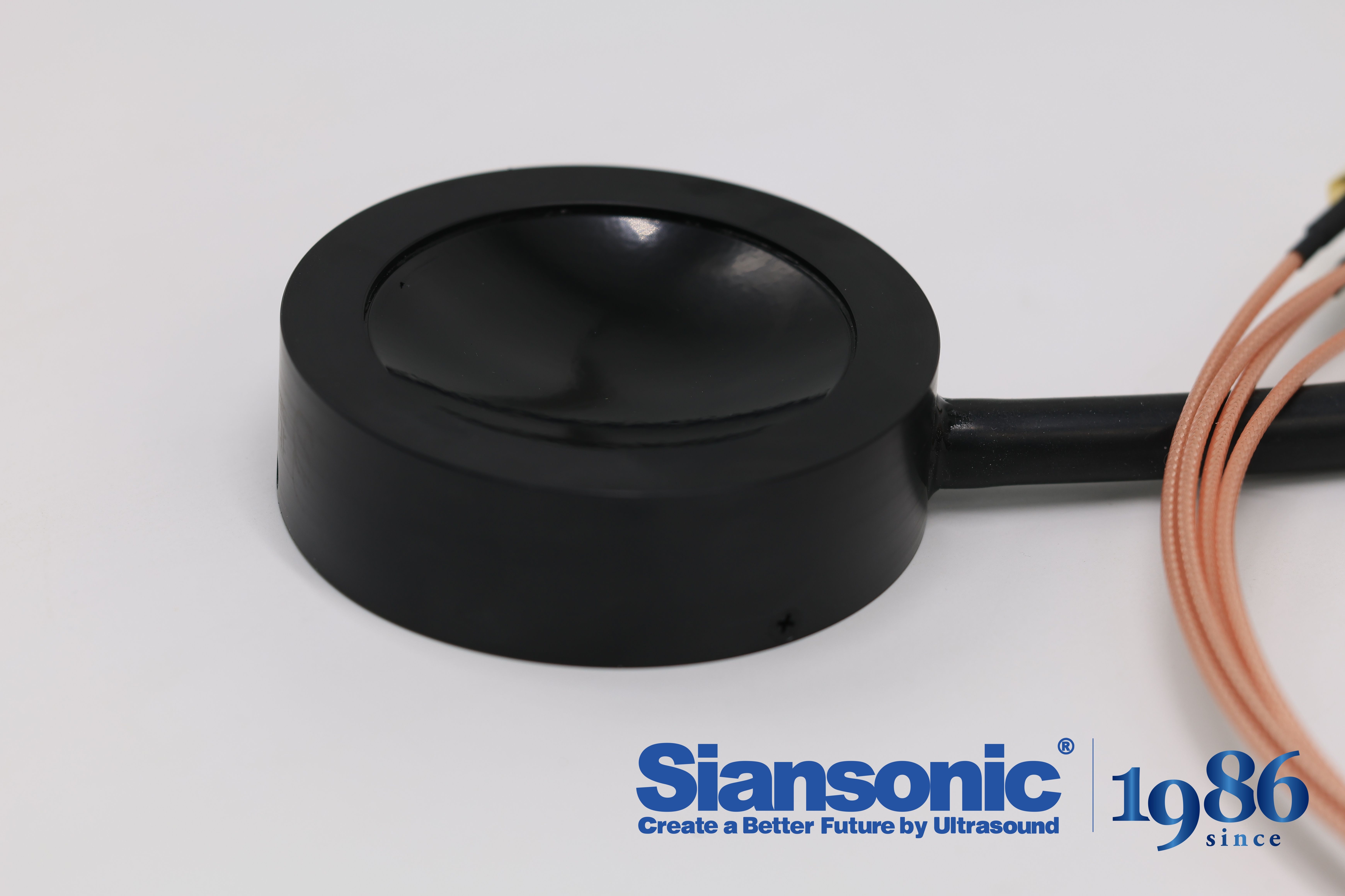
Acoustic components live and die by their physical geometry. A transducer housing that's off by five microns might shift the resonant peak enough to color the entire output. Tight tolerance machining doesn't just keep parts within spec—it locks every bore, flange, and mating surface into a repeatable acoustic signature. When the air gap stays constant and the diaphragm seats exactly where it was designed to, the sound you get on unit one is the sound you get on unit ten thousand.
Most shops can hit tight numbers on a drawing. What separates consistent acoustic parts is how those numbers are held across a full production run. That means controlling tool wear, thermal drift, and fixturing pressure during milling and turning. It also means verifying the finished geometry with in-process metrology rather than trusting a final inspection to catch a drift that already happened. For acoustic assemblies, even a small burr left at the edge of a port can introduce turbulence that shows up as distortion.
The payoff comes when the finished product leaves the line. With every dimension locked down, there's no need to hand-tune each driver or sort parts by frequency response. Assembly time drops, rejects disappear, and the acoustic output stays within a narrow band from batch to batch. That kind of repeatability isn't just a manufacturing convenience—it's what makes a product sound the same in the field as it did in the prototype room.
In-Process Resonance Checks to Catch Drift Early
Resonance data is one of the fastest ways to see a process drifting before dimensions or surface finish show any change. A part’s natural frequencies depend on stiffness, mass distribution, and how it’s held, so even small shifts in clamping pressure, material batch, or tool wear move those peaks. By checking resonance at a mid-process station, you get a warning while the part is still in your hands—not after it has become a completed assembly that’s expensive to rework.
The check itself doesn’t need to be complicated. A short, controlled tap or a swept sine excitation through a small shaker is usually enough. An accelerometer or laser vibrometer captures the response, and the system compares the dominant modes to a stored baseline. If the frequency of a key mode moves outside a narrow band, the line stops or marks the part for a quick fixture check. This keeps the response fast enough for high-mix production without turning quality control into a bottleneck.
One practical advantage is that resonance checks often detect problems that other in-process gauges miss. For example, a slightly loose insert or a worn spindle bearing may not change a measured diameter right away, but it will shift the damping or a higher-order mode. Catching that drift early means you can adjust the process while the effect is still local—retorque a clamp, change a tool, or tweak a feed rate—instead of discovering a full shift of bad parts at final inspection.
Thermal Cycling Validation Before Final Sign-Off
Before any product gets the final sign-off, thermal cycling validation is where hidden weaknesses usually surface. We've seen boards pass room-temperature checks only to crack solder joints within a few dozen cycles when the temperature swings between -40°C and 85°C. The key is to mimic real-world stress, not a gentle lab ramp. A ramp rate of 5°C per minute with a 30-minute dwell at each extreme exposes CTE mismatches between the die, substrate, and PCB far better than slow, lazy cycles that let stresses relax too easily.
Placement of thermocouples matters more than most teams admit. Attaching them to the package corner, the board center, and the highest-mass component gives you a true picture of thermal lag. You'll often see a 10–15°C difference between the air temperature and the actual junction temperature during transitions. If you're only logging chamber air, you're blind to the real strain on the silicon. We also monitor daisy-chain resistance continuously—an occasional spike can indicate a cracked via or a failing bump long before it becomes a hard open.
The final pass/fail line shouldn't be arbitrary. For consumer electronics, 500 cycles might be enough, but automotive or aerospace hardware often needs 1,000 cycles with no resistance shift beyond 10%. And don't sign off just because the sample survived—check the failure mode. A single crack in a corner ball may be acceptable if redundancy exists, but a lifted pad under a BGA is a board design problem that will come back to haunt you in the field. That last review of post-cycle cross-sections is what turns a box-ticking exercise into actual confidence.
Operator Certification Programs Beyond Basic Soldering
Many assembly teams treat soldering certification as a one-time checkbox, but stronger programs push operators into board-level diagnostics, rework planning, and mixed-technology handling. This shift becomes necessary when a line moves between through-hole, surface mount, and fine-pitch components during the same shift.
A robust operator certification path usually layers IPC-A-610 or J-STD-001 criteria with live process audits and defect analysis. Instead of only passing a coupon test, operators read real boards, identify latent faults like head-in-pillow or insufficient barrel fill, and document corrective actions. That practical judgment is what separates a certified operator from someone who simply knows how to form a fillet.
Some facilities add specialized endorsements for reflow profiling, selective soldering, wire prep, or conformal coating touch-up. These micro-credentials keep the training tied to actual production bottlenecks rather than generic modules. Operators rotate through a short supervised evaluation, then get recertified based on observed work quality and first-pass yield trends, not just written exams.
Traceable Material Batches for Every Wafer and Wear Plate
Every wafer and wear plate we ship is tied to a specific material batch record that follows the raw stock from the mill through final inspection. The batch ID appears on the physical part label and in the digital certificate, so a quick scan or manual lookup reveals the exact heat number, supplier lot, and processing date for that individual unit. This means you never have to guess which delivery a particular plate came from or wonder whether it was part of a mixed lot.
When a deviation shows up on the line, the batch trace lets you pull only the affected pieces instead of halting an entire inventory. Our records also include hardness readings, thickness measurements, and surface finish notes for each batch, making it easier to compare performance across different runs. Over time, those data points help you spot subtle shifts in wear behavior before they turn into unplanned downtime.
FAQ
It usually comes down to how seriously the factory treats environmental controls. Temperature swings and humidity shifts can subtly change piezoelectric ceramic dimensions and adhesive curing, so leading facilities keep assembly areas within narrow bands and log conditions continuously rather than spot-checking.
They avoid rushing the bonding step. Instead of relying on a single adhesive batch, they pre-condition substrates, apply primers under controlled viscosity, and use vacuum degassing to eliminate microvoids. After curing, acoustic microscopy or scanning acoustic tomography checks for hidden voids before the transducer ever reaches final test.
Final checks only catch gross failures. In-process impedance sweeps after poling and after each assembly stage reveal shifts in resonance frequency or mechanical quality factor that signal weak bonds, cracked ceramics, or inconsistent preload. Catching these early lets workers adjust torque or alignment before units are potted, reducing scrap and field returns.
Preload keeps the piezoelectric stack under compression during high-power operation. If it varies from unit to unit, some transducers run hot or drift in frequency under load. Factories with strong reliability records use calibrated torque drivers, load cells, or press force monitoring to record the preload value for every transducer, not just a sample.
They characterize incoming ceramic rings or plates with a quick resonance and capacitance measurement, then group them into narrow performance bins. Each production batch is matched to a specific bin so the tuning inductance and matching network stay within tolerance. This avoids re-tuning every transducer and keeps the line moving.
A staged cleaning protocol works best: aqueous ultrasonic wash with mild detergent, followed by deionized water rinse, isopropyl alcohol wipe, and plasma or UV-ozone treatment just before bonding. The key is verifying surface energy with dyne pens or contact angle checks, because visually clean surfaces can still have residues that weaken adhesion.
Thermal cycling exposes latent defects like poor solder joints, mismatched thermal expansion, or incomplete adhesive cure. By cycling between operational extremes and then re-testing impedance and capacitance, the factory weeds out units that would fail after a few months in the field. It is cheaper to catch them in-house than to process returns.
They embed traceability early with laser-marked serial numbers on components or use barcode-scanned work orders at each station. Test data—impedance curves, capacitance, preload force, leak test results—are auto-logged against that serial number. This creates a digital thread without manual paperwork, so traceability adds minutes, not hours, per unit.
Conclusion
Cleanroom assembly protocols do more than keep dust off piezoceramic elements; they preserve the exact surface energy needed for consistent bonding and electrode integrity. Tight tolerance machining then translates that care into repeatable acoustic output—every housing bore and matching layer thickness is held to micron-level specs, so transducers deliver the same frequency response batch after batch. In-process resonance checks catch drift early by measuring impedance and phase angle at multiple points along the line, flagging any element that starts to deviate before it becomes a field failure.
Thermal cycling validation before final sign-off pushes each unit through temperature extremes that mirror real-world operating conditions, exposing latent stress cracks or adhesive voids that static tests miss. Operator certification programs go beyond basic soldering: technicians must demonstrate proficiency in bonding, tuning, and interpreting resonance spectra, with annual re-certification tied to specific failure modes. Finally, traceable material batches for every wafer and wear plate mean that if a problem ever surfaces, the exact lot of PZT ceramic or matching layer can be pulled from inventory and cross-referenced with assembly records—turning a potential recall into a targeted correction.
Contact Us
Contact Person: Ivy Zhang
Email: [email protected]
Tel/WhatsApp: +86 1081502288
Website: https://www.siansonic.com/