

Professional Through Hole Resistor Selection Tips for Circuit Design
2026-07-19
Choosing the right through-hole resistor might seem trivial, but one wrong pick can send your circuit’s precision down a noisy path. From thermal drift to tolerance trade-offs, every detail matters—especially when low resistance and high accuracy are non-negotiable. Whether you're fine-tuning a power supply or laying out an analog front-end, these practical tips will help you navigate the spec sheets with confidence. For more in-depth guidance, Milliohm has the resources you need to get it right the first time.
Beyond the Ohm Value: Matching Resistors to Real-World Conditions
Selecting a resistor based solely on its ohm value is like choosing a car by its top speed—it misses almost everything that matters in day-to-day performance. The resistance figure is just a starting point, and in real circuits, factors like tolerance, temperature drift, and power handling often overshadow the nominal value. A 10 kΩ resistor might measure 10.2 kΩ on a warm board, or it could drift completely out of spec under a pulse load if its thermal mass is too low. That’s why experienced engineers treat the datasheet’s environmental derating curves and pulse-handling graphs as essential as the resistance itself.
Among the most overlooked parameters is the temperature coefficient of resistance (TCR). In precision analog circuits, even a 50 ppm/°C shift can degrade a 16-bit ADC’s linearity when the resistor self-heats or the ambient temperature swings. Beyond that, voltage coefficient—the subtle change in resistance with applied voltage—can introduce distortion in high-impedance dividers, yet it’s rarely specified on generic parts. Then there’s parasitics: a wirewound resistor might look ideal for a current-sense application until its inductance turns a fast-switching node into a ringing nightmare. The real world isn’t steady-state DC; it’s full of transients, humidity, and board flex that can push a resistor outside its comfort zone.
Matching resistors to actual use cases demands thinking about the entire signal chain and physical environment. If the resistor sits near a hot voltage regulator, derating the power rating alone won’t save it from long-term drift. Moisture ingress can alter surface-mount thin-film resistors in outdoor equipment, causing year-over-year deviations that no simulation predicts. Even the termination material (e.g., silver-palladium vs. nickel-barrier) can become a failure point under sulfur-rich atmospheres. Taking time to interrogate these non-ideal behaviors pays off in reliability and precision, sparing you from field returns that trace back to a humble part everyone assumed was “good enough.”
Power Ratings Are Just a Starting Point—Here’s What Really Matters
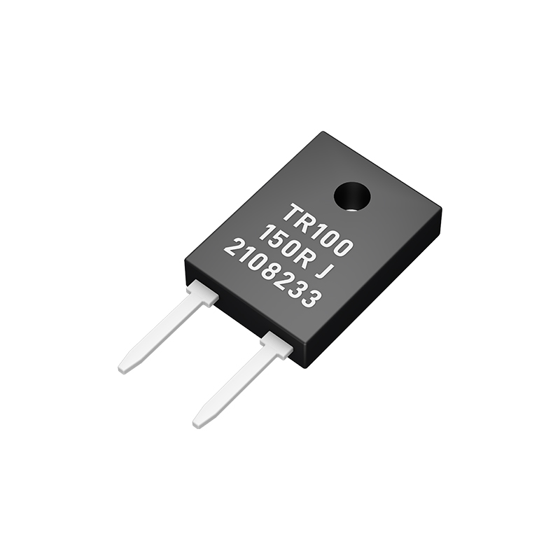
It's easy to get caught up in comparing raw wattage numbers, but those figures rarely tell the full story. A high power rating on paper can be misleading if the underlying design can't sustain that output without excess heat or voltage drops. In practice, a more modestly rated unit with superior components, tighter voltage regulation, and quieter operation often delivers a smoother, more reliable experience than a flashy high-wattage alternative that crumbles under sustained load.
What truly separates adequate from exceptional is how that power is converted and maintained over time. Efficiency at typical usage levels, transient response when demands shift suddenly, and the quality of internal protections against surges or overheating matter far more once a device is inside your case. Instead of fixating on a single headline number, consider the engineering behind the rating—the capacitors, cooling solutions, and circuit topology that determine whether a product will thrive or merely survive in your specific setup.
Tolerance Traps: Why Tight Specs Can Backfire in Production
Over-tightening dimensional tolerances is often a well-intentioned move toward perfection, but it can backfire spectacularly on the factory floor. When drawing tolerances shrink to single-digit microns without a clear functional need, manufacturers are forced into costly process gymnastics—slower cycle times, specialized tooling, and 100% inspection—that eat away at margins without delivering proportional value. Worse, the false sense of precision can mask real performance issues, because a part that meets an arbitrary tight spec may still fail in assembly due to thermal expansion or material creep that were never considered.
The ripple effects extend beyond the machine shop. Supply chains crack under the pressure when second- or third-tier suppliers simply cannot hold the demanded tolerances consistently, leading to late deliveries, rejected batches, and a culture of waivers that erode engineering credibility. In many cases, what was meant to guarantee quality instead creates a brittle process where any slight drift causes a line shutdown. Seasoned engineers learn to push back and ask, "What actually drives function here?"—shifting the conversation from number-chasing to true functional dimensioning.
Smart organizations design for producibility by making tolerances as wide as the function allows, and then controlling critical features with process capability data instead of heroic inspection. This doesn't mean relaxing everything indiscriminately; it means aligning specification boundaries with real failure modes. The result is a more robust supply base, fewer surprise non-conformances, and products that perform reliably because the specs reflect actual physics, not optimistic ambition.
Lead Length and Layout: The Quiet Killers of Stability
A circuit might hum along perfectly on the bench, yet turn erratic once nestled into its enclosure. More often than not, the culprit isn't a faulty component but the humble wire or trace carrying signals between sections. The physical distance a signal must travel, and the path it takes alongside other conductors, can quietly chip away at performance. Even a few extra centimeters of lead can introduce parasitic inductance and capacitance, subtly distorting waveforms or inviting noise into sensitive nodes.
Layout choices compound these effects in ways that aren't always obvious during simulation. A return current that detours widely around a ground plane gap effectively lengthens the loop, turning a benign connection into a radiating antenna. High‑impedance nodes become unwitting pickups for nearby clock lines, while parallel runs of equal length create resonators at specific frequencies. The geometry of a trace—its width, thickness, and proximity to a solid reference—dictates its characteristic impedance, and a mismatch at the destination reflects energy back toward the source, corrupting signal integrity.
Stability in analog circuits, and even in high‑speed digital ones, hinges on understanding that every conductor is a component with its own RLC equivalent model. A long wire feeding a high‑Q LC tank can pump in just enough phase‑shifted energy to sustain a stubborn oscillation. Switching loops with high dI/dt induce ground bounce that corrupts nearby references. The fix often lies not in adding more shielding or filtering, but in simply shortening that lead, re‑routing it further from aggressors, or making the return path a mirror image. It’s a quiet discipline: respect the wires, and they’ll give you a quiet circuit in return.
Temperature Drift: The Silent Performance Eroder
Even the most meticulously engineered devices can’t escape physics. As components heat up or cool down, their electrical characteristics shift subtly—resistance values wander, semiconductor junctions behave differently, and reference voltages inch away from their calibrated levels. It’s not a fault you can spot during a quick bench test, but over hours or days of continuous operation, these tiny changes accumulate into measurable signal degradation.
This creep often goes unnoticed until repeatability suffers. A sensor that reads true on a cold Monday morning might drift by millivolts by Wednesday afternoon, pushing data toward the edges of acceptability. In high-precision measurement chains, even a whisper of thermal instability is enough to erode long-term trust in the numbers. Yet many design reviews treat temperature drift like a checkbox item—something “handled” by a one-time calibration—rather than a dynamic adversary that shifts with ambient conditions, thermal load, and airflow disruption.
The real danger is how silently it works. It rarely triggers alarms or hard failures; it just nibbles at accuracy until the system’s output becomes an approximation of what it once delivered. Engineers who treat drift as a living variable—compensating continuously, characterizing behavior across real-world thermal cycles, and designing for thermal symmetry—are the ones who keep their systems on the right side of that erosion curve.
When Standard Resistors Aren’t Enough: Navigating Custom Options
Off-the-shelf resistors cover a broad range of applications, but there are times when the standard values, power ratings, or form factors simply won’t cut it. Maybe your design requires a very specific resistance value with ultra-tight tolerance, or you need a component that can handle extreme temperatures that go well beyond commercial specs. In high-precision analog circuits, custom resistors—whether they are thin film networks, foil-based devices, or wire-wound with non-inductive winding—can dramatically improve overall system accuracy and stability. The decision to go custom usually hinges on a handful of technical requirements that mass-produced parts cannot satisfy, but it also opens up a conversation about lead times, minimum order quantities, and long-term reliability testing that you don’t have to think about with catalog items.
Navigating the path to a custom resistive component often starts with a deep dive into the real operating conditions your product will face. Is it just about precision at a single temperature, or does the resistance need to remain flat across a wide temperature swing after many thermal cycles? Do you need a non-standard footprint because of a densely packed board, or perhaps an unusual mounting scheme such as bolt-on termination for high-current paths? Engaging with a manufacturer’s application engineers early in the design phase is key—they can suggest specific materials (like nichrome, tantalum nitride, or bulk metal foil) and construction techniques that balance performance against cost. You’ll also want to discuss testing protocols: what parameters are guaranteed beyond the initial datasheet numbers, and how drift over time is characterized.
Of course, custom doesn’t always mean starting from scratch; sometimes it’s about repurposing an existing platform with small tweaks. Many resistor houses offer semi-custom solutions where they modify an established series—adjusting the resistive element geometry, adding heat sinks, or changing the encapsulation—to meet your needs without the full NRE charge of a completely bespoke part. Before committing, ask for samples and qualification data, and consider whether a future shift in your design could make that custom part a bottleneck. If the application is truly one-of-a-kind, a well-specified custom resistor can be the linchpin that makes the whole system work reliably in the field, but it pays to go in with clear technical requirements and a realistic timeline.
FAQ
The main factors include resistance value, power rating, tolerance, temperature coefficient, and physical size. You also need to consider the operating environment, such as temperature extremes and humidity, which can affect long-term stability.
The power rating indicates how much power the resistor can safely dissipate without damage. It's crucial to choose a resistor with a power rating higher than the maximum expected power in the circuit, usually with a safety margin of at least 50%.
Tolerance specifies how close the actual resistance is to the nominal value. For precision circuits, you might need resistors with tight tolerance (e.g., ±0.1%), while general applications can use wider tolerances (e.g., ±5%).
Wirewound resistors are better for high-power applications and have lower noise and better temperature stability. However, they can be inductive, so they're not suitable for high-frequency circuits where carbon film or metal film resistors perform better.
TCR measures how much the resistance changes with temperature. A low TCR is important in circuits that experience temperature variations, such as precision amplifiers or sensors, to maintain accuracy.
The physical size is often related to the power rating—larger resistors can dissipate more heat. Also, you need to ensure the resistor fits on the PCB and doesn't interfere with other components, especially in tight spaces.
Conclusion
Selecting through-hole resistors goes far beyond matching an ohm value to a schematic. Real-world conditions like voltage spikes, humidity, and board flexing demand careful pairing of materials and construction with the environment. A metal film part might shine on the test bench but drift unacceptably under high-frequency stress or thermal cycling, while a humble carbon composition resistor could survive surges that would crater a precision thin-film type. Power ratings are equally deceptive—a data sheet's 0.5 W figure often assumes perfect ventilation and short leads, not a cramped enclosure or prolonged operation near rated limits. Savvy designers habitually derate by 50% or more, accounting for elevated ambient temperatures and grouping effects, and they confirm that pulse-handling capability aligns with actual inrush or transient loads. Tolerance can be another trap: chasing 0.1% specs may inflate cost and lead time without improving circuit accuracy, especially when board parasitics and amplifier offset voltages dominate errors. Sometimes a 1% part plus a simple calibration step in production yields a more consistent and affordable outcome.
Mechanical details like lead length and layout often become silent stability killers. Unclipped leads add unwanted inductance and parasitic capacitance, distorting high-frequency behavior, while mounting resistors too close to a hot regulator or power transistor accelerates thermal aging and shifts values. Even the soldering process matters—prolonged dwell times can permanently tweak resistance. Temperature drift acts as a gradual performance eroder, with coefficients like 50 ppm/°C translating into measurable errors in precision analog paths once the case temperature climbs just a few dozen degrees. When standard catalog parts can't tick all the boxes, custom through-hole resistors become a practical fallback. Nonstandard winding pitches, matched pairs with defined tracking, or oddball form factors can tame layout constraints without sacrificing reliability. The key is weighing the non-recurring engineering effort against the gain in noise immunity or long-term stability, and working closely with a manufacturer willing to provide detailed pulse rating and aging data instead of just a generic datasheet. This whole-process thinking separates a robust circuit from one that works only on a prototype bench.
Contact Us
Contact Person: Yuying Gao
Email: [email protected]
Tel/WhatsApp: +86 18926013721
Website: https://en.milliohm.net/